| Nominal Input Voltage | 24V to 48 Volts |
| Absolute Maximum Voltage | 60 Volts |
| Undervoltage Cut-Off | 20 Volts |
| Peak Battery Current | 50 Amps |
| Peak Phase Current | 55 Amps |
| Input Capacitance | 0.45 mF |
| Controller Efficiency | >90% |
| Max Ambient Temperature Supported | -20 to 50 degC |
| Storage Temperature | -40 to 75 degC |
| Thermal Cutback | Derating Starts at 85 degC and complete cut-off happens at 95 degC |
| Communication Protocol | CANOpen, TTL232, Bluetooth Options Available |
| IP rating | IP67 not including connectors Connectors to be IP Rated at OEM end with suitable potting compounds |
| Controller Type | Field Oriented Control (FOC) for Smooth and Quiet Running |
| Control Mode | Speed Mode, Torque Mode and Torque Mode with Speed Limiting |
| Sensor Support | Hall Sensors, Sensorless and Sin/Cos Encoder |
| Regenerative Braking | Available |
| Heat Sink | Liquid Cooling or External Plate Required, Flat Base Plate with Ra 1.6 finish available. To be used along with thermal compound. |
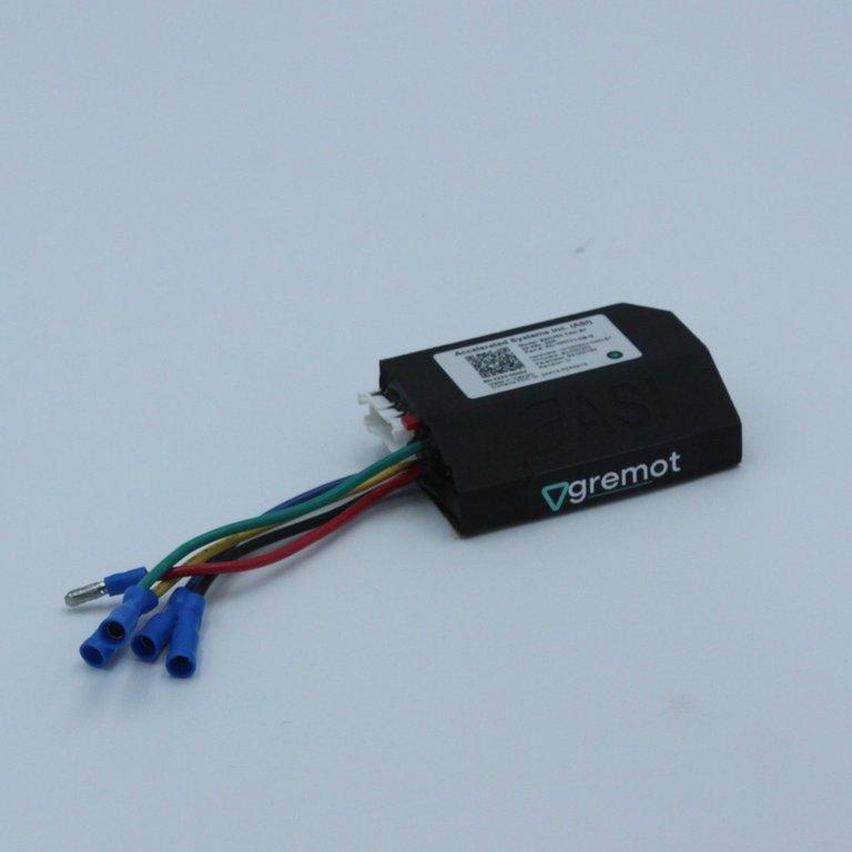
24 PIN JST PAD CONNECTOR
Mating Connector: JST PADP-24V-1-S-24
(Part #: JST SPH-001TT-P0.5L4)
| PIN # | COLOR | FUNCTION | FUNCTION (CLASSIC) | SPECIFICATIONS & RATINGS |
|---|---|---|---|---|
| 1 | Black | Hall GND | Hall GND | 20mA max |
| 2 | White/Black | Hall 5V output | Hall 5V output | 20mA max |
| 3 | Green | Hall-A | Hall-A | 0V ON, 5V OFF |
| 4 | Blue | Hall-C | Hall-C | 0V ON, 5V OFF |
| 5 | Black | GND | GND | 400mA max (shared between all grounds) |
| 6 | Yellow | Hall-B | Hall-B | 0V OFF, 5V ON |
| 7 | Purple/White | Analog input 4 | ABMS | 0-10V (pulled down) |
| 8 | Orange/White | Analog input 3 | Brake 2 | 0-5V (pulled up) |
| 9 | Blue/Black | Digital input 2 | PFS | Pulled up, active low |
| 10 | Orange | Analog input 2 | Brake 1 | 0-5V (pulled up) |
| 11 | Red/White | 5V output | 5V output | 50mA max |
| 12 | Blue/White | Digital input 1 | Cruise | Pulled up, active low |
| 13 | Brown | 12V output | 12V output | 90mA max |
| 14 | Purple | Analog input 1 | Throttle | 0-5V (pulled down) |
| 15 | Purple/Black | Low side switch | HDQ | 100mA max |
| 16 | Black | GND | GND | 400mA max (shared between all grounds) |
| 17 | Grey/White | TTL-RX | TTL-RX | 5V TTL |
| 18 | Yellow/White | TTL-TX | TTL-TX | 5V TTL |
| 19 | Grey/Black | CAN-L | CAN-L (optional 485-A, TTL2-Rx) | 120 Ohm termination resistor (when configured for CAN) |
| 20 | Yellow/Black | CAN-H | CAN-H (optional 485-B, TTL2-Tx) | 120 Ohm termination resistor (when configured for CAN) |
| 21 | Red | B+ output | Key-out | Always live connected to Controller B+ |
| 22 | White | Controller enable input | Key-in | Requires B+, may draw up to 100mA |
| 23 | Green/White | 6V switchable output | 6V Light | 500 mA max (only for light) |
| 24 | Black | Power GND | Light GND | 500 mA max (only for light) |
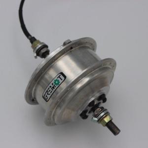
Power and Phase Connections
KST Bullet Male Blue -MPD2-156 / Female Blue -FRD2-156
KST Bullet Male Yellow- MPD5.5-195 / Female Yellow-FRD2-5.5-195
INPUT SPECIFICATIONS
| TYPE | QTY | VOLTAGE | VMIN | VMAX |
|---|---|---|---|---|
| Hall sensor inputs | 3 | Logic High | 0 VDC | 0.5 VDC |
| Logic Low | 3.5 VDC | 5 VDC | ||
| Digital inputs | 2 | Logic High | -0.3 VDC | 1.5 VDC |
| Logic Low | 4 VDC | 5.3 VDC | ||
| 5V analog inputs | 3 | Analog | 0 VDC | 5 VDC |
| 10V analog inputs | 1 | Analog | 0 VDC | 10 VDC |
3D Drawing
Click to view/download the 3D Drawing. Available in a variety of formats for all modelling software.
View 3D (CAD)